|
 MANUAL
Dipmeter
Calculations
MANUAL
Dipmeter
Calculations
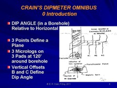
Although it is seldom done anymore, manual dipmeter calculations
with a scientific calculator is quite practical and instructive.
The technique given below was presented by R. Bateman and C. Konen
in "The Log Analyst and the Programmable Calculator" in The
Log Analyst, Jan 1978. The method is based on hand
measurements of curve offsets from the raw dipmeter curves
and readings from the hole direction data. These equations
are for the four arm dipmeter and ignore closure and
planarity errors. The position of the angles in space is
shown below.

Definitions for dipmeter calculations
For
low angle dipmeter:
1: PAZ = AZ1 + MD
2: HAZ = AZ1 - RBR + MAGD
For
high angle dipmeter:
3: PAZ = AHD + RBR + MAGD
4: HAZ = AHD + MD
Adjust
angles to fit between 0 and 360 degrees:
5: PAZ = 360 * Frac ((PAZ +360) / 360)
6: HAZ = 360 * Frac ((HAZ +360) / 360)
Note:
All azimuth angles are measured positive clockwise, with north
at zero (if appropriate).
The
curve offsets are measured in inches or millimeters of log paper
and translated into dip angles across orthogonal pad pairs:
7: ANGLA = Arctan (SCALE * H13 / D13)
8: ANGLB = Arctan (SCALE * H24 / D24)
Note: Curve offsets are positive measuring upward from pad 1 to
pad 3 and from pad 2 to pad 4.
Note:
SCALE is the scale of the log film, ie. a 1:20 scale log (60 inches
= 100 feet) has SCALE = 20. For example an offset of 0.25 inches
of paper is really 20 * 0.25 = 5 inches of borehole.
Project
these two dips onto the dip plane to find apparent dip and azimuth:
9: ADM = Arctan (((Tan ANGLA)^2 + (Tan ANGLB)^2)^0.5)
10: ANGLD = Arccos (Tan ANGLA / Tan ADM)
11: IF H24 < 0
12: THEN ANGLD = 360 - ANGLD
13: ANGLD = ANGLD + PAZ
14: ADAZ = 360 * Frac ((ANGLD + 360) / 360)
Translate
apparent dip to true dip:
15: DIP = Arccos(Cos WD * Cos ADM + Sin WD * Sin ADM * Cos(ADAZ
- HAZ))
16: ANGLG = Arccos ((Cos ADM - Cos WD * Cos DIP) / (Sin WD * Sin
DIP))
17: IF Sin (ADAZ - HAZ) >= 0
18: THEN AZM = HAZ + 180 - ANGLG
19: OTHERWISE AZM = HAZ - 180 + ANGLG
20: AZM = 360 * Frac ((AZM + 360) / 360)
In a July 2017 email, Charles Berg at ResDip pointed out that
DIP could exceed 90 degrees and that we usually do not report
dips this way. An additional step provided by Charles corrects
this problem:
21: IF DIP > 90
22: THEN DIP = 180 - DIP
23: AND AZM = 180 + AZM
Note:
All dip angles are measured from horizontal, down to the dipping
plane.
Where:
ADAZ = apparent dip azimuth from true north
ADM = apparent dip magnitude
AHD = azimuth of hole deviation relative to magnetic north
ANGLA = dip angle between pads 1 and 3
ANGLB = dip angle between pads 2 and 4
ANGLD = apparent dip azimuth from pad 1
ANGLG = apparent dip azimuth before tool orientation
AZ1 = azimuth of pad 1 relative to high side of hole
AZM = true azimuth of dip direction
DIP = true dip angle
D13 = hole diameter between pads 1 and 3 (inches or mm)
D24 = hole diameter between pads 2 and 4 (inches or mm)
HAZ = azimuth of hole direction relative to true north
H13 = offset between events on dip curves 1 and 3 (inches or mm)
H24 = offset between events on dip curves 2 and 4 (inches or mm)
MAGD = magnetic declination (East is positive, West is negative)
PAZ = azimuth of pad 1 relative to true north
RBR = relative bearing
WD = well deviation angle
|