|
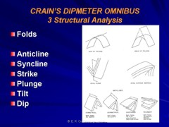
 Dipmeter Calculations With Stereonets
The stereonet is an old, traditional tool for dipmeter analysis
that has become unconventional by the passage of time. Developed
before the days of calculators and computers, it allowed computation
of many complex tasks that were tedious to perform by hand. Numerous
software packages are available now to plot this data more neatly
than can be achieved with pencil and paper.
These
tasks include finding the projection of a plane, direction of
a line normal to a plane, the line of intersection of two planes,
angles between two planes, true dip from two apparent dips and
vice versa, and regional dip removal. Some of these functions
have been described earlier, using the calculator, SCAT, or tangent
diagrams. Some people still prefer the stereonet, but the calculator
is easier.
These
instructions are paraphrased from "Schlumberger Dipmeter
Fundamentals 1981", and the stereonets are copied from the
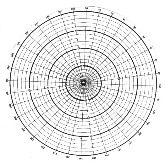
previous edition dated 1970. For working through stereographic
problems you should have a stereonet such as the one shown below, plus pieces of tracing paper large enough to cover it,
or a plastic overlay, made from a xerographic reproduction of
the next illustration. These two illustrations are used for high angle
dips. Enlarged versions of the central
portions of the illustrations are used for low angle
dips (see below).
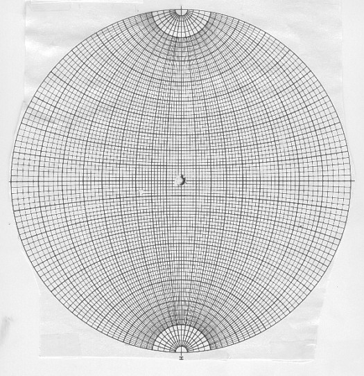
Stereonet for high angle dip
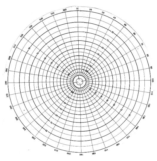
Stereonet overlay for high angle dip (reproduce
on clear film)
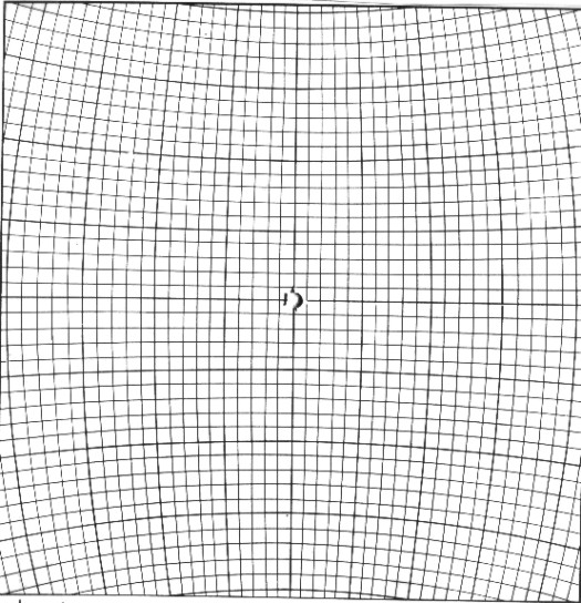
Stereonet for low angle dip
Stereonet overlay for low angle dip (reproduce
on clear film)
The
data for each problem are plotted on the tracing paper or overlay,
and the stereonet is rotated to suit the differing orientations
met with in each case. Although it is usually more convenient
to lay the stereonet down and keep it fixed, while rotating the
tracing paper over it, keep in mind that it is the tracing paper
overlay, and not the net, that represents the fixed Earth.
If
you use tracing paper, trace the outer circle of the stereonet
on it and mark a "north" point with an N on the circle
at some arbitrary point. Tracing the outer circle is necessary
so that the two diagrams - overlay and stereonet - can be kept
concentric in all orientations. You could achieve the same result
by pinning the two layers together so that the tracing paper rotates
about the center point of the stereonet. No matter how the overlay
is rotated, the N point should be regarded as always pointing
north.
If
you use a transparent copy of the overlay,
the circle and north point (0/360 degrees) are already marked.
Use a grease pencil to mark points and lines, so it can be wiped
off before the next example.
To
understand how a stereogram is constructed, imagine standing on
level ground and looking down into a hemisphere contoured at our
feet and extending down into the ground, as if the ground were
transparent. Any plane that passes through the center of a sphere
cuts the spherical surface in an arc called a great circle. If
we stand on an outcrop of a bed dipping down into the ground,
we can imagine that the bed cuts the underground hemisphere with
an arc of a great circle, below, top right.
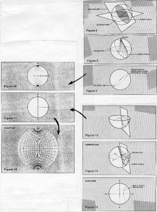
Stereonet - basic concepts
To
project that circle up to the horizontal surface at ground level,
we connect every point on the great circle to the zenith point
of the sphere, above our head. The intersection of the lines with
the horizontal plane form a new circle; many such circles form
the north south grid lines of the stereonet, see above, middle
left.
The
intersections of vertical planes that do not pass through the
center of the sphere intersect the hemisphere surface as small
circles and can be projected up to the stereogram surface, via
the zenith point, exactly as before, see above, lower right.
These form the circles that are centered on the north and south
poles, forming the east west grid on the stereonet. Superposition
of the two sets of circles creates the final stereonet presentation,
see above, lower left.
A
straight line passing downward at a slant through the point at
which we are standing cuts the hemisphere at a point that can
be projected onto the stereogram by the same technique. Again,
the zenith point provides the reference for the projection, see
below, top right. Both lines and planes can be plotted on the
same diagram, see below, middle right. Horizontal and vertical
planes are special cases; the projection of a horizontal plane
is the outer edge of the stereonet, a vertical plane passing through
the center is a straight line, below, lower right.
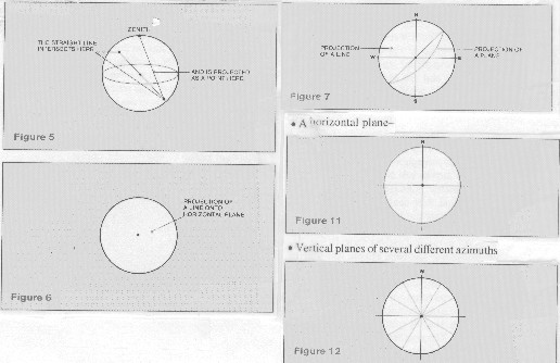
Lines and planes on the stereonet
Illustrated below at upper left is how to plot the projection of a plane
dipping 20 degrees in a N 40 degrees E direction:
1. trace the outer circle of the stereonet onto the overlay and
mark a "north" point on it. It helps to add the other
cardinal points and the center.
2. find N 40 degrees E on the edge of the stereonet and mark this
point on the overlay. A line drawn between this point and the
center represents the direction of dip of the plane.
3. find a great circle appropriate to a dip in this direction
by rotating the overlay until the N 40 degree E dip line lies
along the east-west diameter. It doesn't matter whether you choose
to point the dip line toward the east or the west, because we
are going to return it to its rightful orientation later.
4. now trace in the great circle arc corresponding to 20 degrees
of dip. The outer circle of the stereonet represents zero dip,
so count the 20 degrees inwards from the edge. Do not use the
dip angles marked on the overlay - they count degrees in the opposite
direction.
5. finally, rotate the overlay back to bring north to the top.
The curve on the overlay now represents the great circle which
describes a dip of North 40 degrees East.
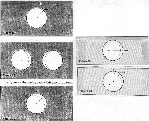
Projection of a plane
Lower right shows how to plot the direction of the line
normal to the surface of the plane in example 1.
1. rotate the overlay on the stereonet to place the dip line onto
the east-west axis.
2. the normal to a plane makes a 90 degree angle to the plane
in all directions; therefore count 90 degrees from the great circle
projection along the east-west diameter and mark point P.
Note
that it doesn't matter in which direction you count along the
diameter; if you should choose the direction that brings you to
the edge of the net before reaching 90 degrees, jump to the other
end of the diameter and finish counting from there. Check that
both directions bring you to point P.
3. rotate the overlay back to the position with north at the top,
and check that point P lies in the southwest quadrant, as you
would expect.
4. this point, which represents the direction of the line normal
to the given plane, is called the "pole" of the plane.
The
image below, upper left, shows how to find the line of intersection
of two planes: Given: plane A dips 20 degrees toward N 40 degrees
E (the plane in example 1). plane B dips 30 degrees towards N
20 degrees W.
1. plot the projections of these planes on the stereonet as in
example 1.
2. point P is the point of intersection of these two curves, and
it therefore represents the projection of the line of intersection.
3. rotate the overlay to bring point P to the north-south diameter
of the stereonet, and read off its bearings. Count inward from
the edge to find the dip angle and observe the direction along
the edge of the stereonet. The line of intersection dips about
19 3/4 degrees in a direction 31 degrees east of north.
Line of intersection of two planes
Middle right,
above, shows how to find the angle between the two
planes in the previous example. Given: plane A dips 20 degrees
toward N 40 degrees E (the plane in example 1). plane B dips 30
degrees towards N 20 degrees W.
1. find the poles of the two intersecting planes (PA and PB),
and also the great circle for which the point of intersection,
P, is the pole. Notice that PA and PB both lie on this great circle,
which follows from the fact that the plane normal to the line
of intersection must also be perpendicular to both the given planes.
Hence their poles lie on its great circle when plotted on the
stereonet.
2. find the dihedral angle between the planes, by either:
a. measure the angle between PA and PB, or
b. measure the angle between the original planes directly, using
the third great circle as the measurement path.
Both
methods should give the same answers, of course. Notice, however,
that with the first method the angle measured directly between
PA and PB is 26 degrees, while the angle between the great-circle
arcs is 154 degrees. Because 26 degrees + 154 degrees = 180 degrees,
we know that 26 degrees is the acute dihedral angle and 154 degrees
is the obtuse dihedral angle between the given planes.
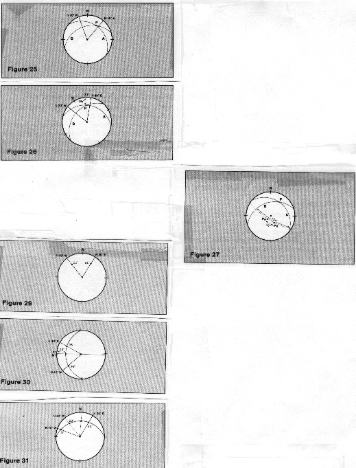
The bottom left
illustration shows how to find true dip from dip measured
in two different vertical planes: Given: dip A is 25 degrees,
in a plane N 30 degrees E and dip B is 20 degrees, in a plane
N 40 degrees W
1. plot these measured dips on the stereonet.
2. rotate the overlay until you find, by trial, the position for
which these two points lie on the same great circle, and trace
in that great circle arc.
3. true dip angle and azimuth, 28 degrees at N 3 degrees E, can
then be read directly from the stereonet.
Notice
that this procedure can be worked backwards, to find the slope
of a bed on any azimuthal direction if the true dip is known.
First trace in the great circle for the bedding plane, knowing
its dip; then find where this arc cuts a radial line drawn with
the desired azimuth. You would need to do this twice to find transverse
and longitudinal dip components.
If
an inclined formation contains smaller bedded units within it,
the computed dips of the subunits need to be corrected, by subtraction
of the dip of the major system, to find their dips at the time
of deposition. For the stereonet, the problem is that of rotating
one plane by an amount, and in a direction, given by the dip of
the other.
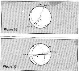 The
image at the right shows how to eliminate structural dip from
computed dip. Given: formation dip of 30 degrees, azimuth N 20
degrees E structural dip of 15 degrees, S 40 degrees W The
image at the right shows how to eliminate structural dip from
computed dip. Given: formation dip of 30 degrees, azimuth N 20
degrees E structural dip of 15 degrees, S 40 degrees W
1. plot the plane of the regional dip and add P, the pole of the
formation dip.
2. rotate the structural plane to the horizontal by moving its
projection until it lies entirely on the outer circle of the stereonet.
3. rotate the other plane through the same angle, which means
moving its pole, point P, across the stereonet by the same distance
and in the same direction as we move the projection of the structural
plane. Be careful to measure "distance" in degrees and
use the small circle arcs as guides to direction. So when the
major plane rotates 15 degrees back to the horizontal, point P
must move 15 degrees along a small circle arc to position P1.
4. the dip of the sedimentary unit at the time of deposition was
46 degrees, azimuth N 25 degrees
|