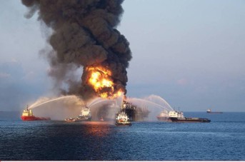
Because the survey is taken in a wellbore, it is considered to be part of the well logging process and is often run by logging service companies after the more conventional logs and seismic reference survey are completed. In many cases, the VSP replaces the checkshot survey because, if properly designed, the same information can be extracted from VSP records as from SRS records. Since the geophones are down the hole, surface distortions which affect conventional seismic are reduced. This comparatively noise free environment means that the VSP traces are less noisy than a synthetic seismogram made from unedited sonic and density logs. It may even be better than a well edited synthetic because no lithology, wavelet, or filtering assumptions have to be made by the analyst. As a result, VSP's have gradually replaced the synthetic seismogram. There are other advantages, such as being able to see laterally in 3-D around the borehole as well as below the bottom of the well. A well can be sidetracked toward its target based on interpretation of unexpected changes in lithology or structure observed on the VSP. A major use of the VSP is to invert it into a syntetic acoustic impedance log, and use this to predict overpressure below the current depth of the well. The drilling program and mud properties can be adjusted to reflrct overpressure zones detected on the inverted impedance log. The images below demonstrate why you might want to do this on any well in which pressure contril might be an issue.
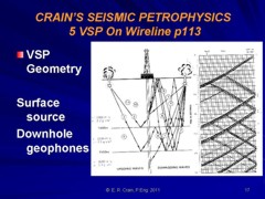
Integrated sonic logs are still needed to fix the precise location of formation tops on the VSP wiggle traces. The technique records both down going and up going seismic signals simultaneously and these must be separated by suitable data processing. This extra information helps to determine the acoustic response of the earth and therefore the lithology near the borehole.
The
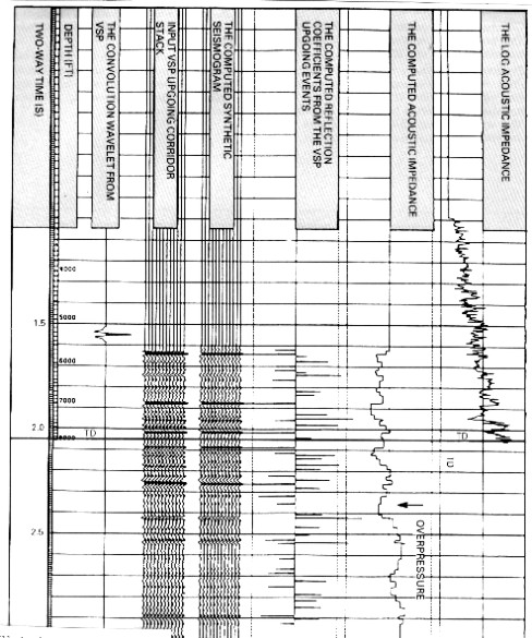
processing sequence is as follows: This sequence and some of the intermediate results are shown below. Some of these operations, such as stacking, band pass filter, and de-convolution can be done in the computerized logging truck at the well site.
Creation of a seismic inversion trace or Seislog from this data is considerably more effective than with conventional seismic because of the broad frequency content and low noise level of vertical seismic data. In addition, the final processed trace at the wellbore is reasonably noise free, which sometimes eliminates the need to create a synthetic seismic trace, and thus reduces the need for log editing and reduces the chance of formation mis-ties.
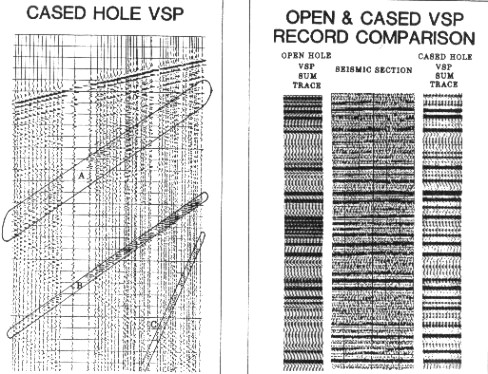
A synthetic VSP can be made, much in the same way as a synthetic seismogram, and used to model various noise free alternative interpretations, from which the correct interpretation or further processing steps might be chosen. Both shear and compressional VSP's can be recorded and modeled. The software is moderately complicated due to the radial geometry and the need to track both up- and down-going signals and their multiples. Cased hole VSP's are a valuable aid in evaluation of older wells. Along with cased hole log analysis for porosity, saturation, and lithology, they provide almost as much information as can be obtained from an open hole evaluation. A comparison of open and cased hole VSP's is provided below.
|
|
||
|
Page Views ---- Since 01 Jan 2015
Copyright 2023 by Accessible Petrophysics Ltd. CPH Logo, "CPH", "CPH Gold Member", "CPH Platinum Member", "Crain's Rules", "Meta/Log", "Computer-Ready-Math", "Petro/Fusion Scripts" are Trademarks of the Author |
|||

|
||
| Site Navigation | TOOL PROFILES VERTICAL SEISMIC PROFILES (VSP) | Quick Links |