|
 CaRBON DIOXIDE BASICS
Selection, evaluation, and monitoring carbon dioxide storage
reservoirs is a multi-disciplined task, in which petrophysics plays
a vital role. Most of the discussion about CO2 also applies to
natural gas (CH4) and hydrogen (H2) storage reservoirs. This article
describes the special properties of CO2, storage reservoir criteria,
the role of petrophysics, followed by visual and quantitative log
analysis methods, and an example from a CO2 monitoring project using
the fast neutron cross section measurement.
Carbon dioxide (CO2) is a chemical compound occurring as a colorless
non-combustible gas with a density about 153% of that of dry air. It
has a sharp and acidic odour and taste at high concentrations (eg
carbonated water), but at atmospheric concentrations it is odourless
and tasteless. Because CO2 is heavier than air, it can collect in
low or enclosed spaces, asphyxiating occupants due to lack of
oxygen.
CO2 has no liquid phase at pressures below 518 kPa. At 101 kPa, the
gas deposits directly to a solid (dry ice) at temperatures below
−78.5°C; the solid sublimes to gas above this temperature. Liquid
CO2 forms only at pressures above 518 kPa. The density of dry ice
increases with decreasing temperature and ranges between 1550 and
1700 kg/m3 below −78 °C.
Most elements and simple compounds can exist in
the gas, liquid or solid phase depending on temperature and
pressure. A few can exist in a fourth phase, as a supercritical
fluid when above a critical temperature and pressure. The critical
point for CO2 is 31.1 C and 7.38 MPa, above which the distinction
between the gas and liquid phase disappears, entering the
supercritical fluid phase. A supercritical fluid behaves like a gas,
moving easily through porous media, but has densities more like
liquids. Density of supercritical CO2 is 600 to 800 kg/m3.
Geological CO2 storage makes use of these special supercritical
properties, allowing for efficient transportation and injection of
CO2 into underground reservoirs.

Phase diagram of carbon dioxide (Wikipedia)
SOURCES AND
USES OF CARBON DIOXIDE
Carbon dioxide occurs naturally in our atmosphere in trace
amounts, about 412 ppm by volume, compared to pre-industrial
levels of 280 ppm. CO2 is one of several green house gases
(GHGs) that are implicated in global warming and climate
change. Reducing CO2 emissions and CO2 capture and storage
(CCS) to mitigate these issues are goals of industry and
government.
Natural sources of CO2 include volcanoes, forest fires, hot
springs, geysers, dissolution of carbonate rocks, and decay
of organic matter, including landfills and backyard compost.
It is soluble in water and occurs naturally in groundwater
and all surface water bodies.
Human sources include combustion of wood, peat and other
organic fuels, fossil fuels, and unwanted by-product of many
industrial processes, such as manufacture of cement, steel,
and plastics. Agriculture and food processing is a large CO2
emitter, mostly unrecognized because it is so dispersed
across the planet.
Major uses of carbon dioxide are as a feedstock for
synthetic fuels and other chemicals. It is used in welding,
fire extinguishers, pressurizing agents, enhanced oil
recovery (EOR), and as a solvent. It is the key ingredient
in carbonated drinks. The solid form (dry ice) is used as a
refrigerant and as an abrasive in a much less messy form of
sand-blasting.
Carbon dioxide is essential for all plant life, which
generates the oxygen essential for human existence. However,
too much of a good thing is turning into a bad thing, so we
must learn to reduce emissions and to store what we can’t
reduce in a safe place, instead of into the atmosphere.
CARBON STORAGE
IN GEOLOGICAL FORMATIONS
Geological sequestration refers to the storage of CO2
underground in depleted oil and gas reservoirs, saline-water bearing
formations, or deep, un-minable coal beds. The storage capacity of
these reservoirs worldwide is enormous, estimated as large as 20,000
Giga tonnes of CO2.
As CO2 is captured from an industrial source, such as a cement
plant, steel mill, or oil refinery, it is compressed to about 10 MPa
so that it becomes a supercritical fluid. In this form, the CO2 is
easy to transport via pipeline to the storage location. The CO2 is
then injected into an underground porous reservoir, where it will
remain as a stable supercritical fluid.
At these storage conditions, the density of
supercritical CO2 is 600 to 800 kg/m3, lighter than water, so it
will rise to the top of the reservoir and be trapped by the caprock
above the reservoir. As more CO2 is injected, it will spread
laterally until the reservoir has been filled to its capacity.
 A good reservoir for carbon dioxide storage is one with medium to
high porosity and permeability, with no faults or fractures, and a
well defined structural or stratigraphic trap. The seal or caprock
is usually a thick shale, an evaporite such as halite or anhydrite,
or a subsurface lava flow like basalt. A good reservoir for carbon dioxide storage is one with medium to
high porosity and permeability, with no faults or fractures, and a
well defined structural or stratigraphic trap. The seal or caprock
is usually a thick shale, an evaporite such as halite or anhydrite,
or a subsurface lava flow like basalt.
Porosity-lithology depth plot
showing evaporite caprock and porous carbonate suitable for a CO2
storage reservoir
If there are faults or fractures, there is a
strong possibility that the CO2 could migrate to other reservoirs,
causing economic loss to others, or a leak to the surface, which
could be dangerous to life in the surrounding area.
The dominant monitoring technique to date is
time-lapse 3-D seismic imaging to locate the CO2 plume in the
reservoir. Well logs run periodically in monitoring wells are also
widely used.
PETROPHYSICS FOR
CARBON STORAGE PROJECTSfs
Petrophysics has a large role to play in the green
economy. Hundreds of thousands of legacy wells have been
drilled in the past, in search of fossil fuels. These wells
penetrate reservoirs which may find new life by defining
potential storage for carbon capture and storage (CCS). The
competent petrophysicist can analyze these old wells with
key suitability criteria in mind, to validate mechanical
earth models (MEM), which tend to be more heavily weighted
towards seismic inputs. Seisic can give a good overview of
the reservoir, but only petrpphysics can fill in the details
that can determine success or failure of the project.
Identifying a container for CO2 is the most
important step in the process; a suitable site ensures the injected
CO2 will stay where it is supposed to be for the foreseeable future.
The key criteria for which petrophysical
analysis can provide ground truth for the reservoir model are: shale
characterization, porosity, permeability, mobility and
saturations. Including legacy wells means better definition of the
areal extent of the potential container. Once the container has been
selected and the most porous snf permeable zones selected for
injection well locations, the petrophysicist will run logs to
evaluate the well for fractures and casing / cement integrity. In
the final phase, the petrophysicist will evaluate the monitor wells
to assess how well the CO2 has entered the pore space.
Due to the risk to life from a CO2 leak to
surface, there is no room for amatuers or novices in this work.
Expert petrophysical advice should be sought and be acted upon at
every stage in the project development and operation.
Here are the stages in the development of a
carbon storage reservoir that require competent petrophysical
analysis, coupled with other geoscience and reservoir engineering
work.
PHASE 1: Find a Suitable Storage
Reservoir
Criteria: thick competent caprock, no faults or fractures, no
barriers to vertical flow (shale or anhydrite interbeds), thick
porous and permeable reservoir (saline water bearing or depleted oil
or gas zone), structural or stratigraphic trap (area, volume, spill
point), economics, proximity to CO2 source.
Action Items: prepare complete reservoir study, integrating
geological, geophysical, and petrophysical analysis (with mechanical
properties calculations) on all available wells (including entire
caprock sequence), prepare structural maps and cross sections, pore
volume calculations, depth-pressure-temperature profiles.
PHASE 2: Locate and Evaluate Injection Well(s)
Action Items: select injection well location(s) based on reservoir
model, drill through best porosity to optimize CO2 injection rate,
run and analyze full log suite, run resistivity image log to find
unexpected fractures, run ultra- sonic cement integrity log to find
leaks or channels, repair as needed. Run Pulsar (induced gamma ray
spectroscopy with fast neutron cross section) for comparison to same
log in monitor wells.
PHASE 3: Run Baseline Well Logs In Monitor Wells
Action Items: In open hole run resistivity image log to find
unexpected fractures. In cased hole, run ultra- sonic cement
integrity log to find leaks, repair as needed. Before CO2 injection
begins, run baseline logs over storage reservoir, entire caprock,
and 1000 meters above caprock.
Option 1: Pulsar log, generically known as the advanced pulsed
neutron log, which includes gamma ray (GR), neutron porosity (TPHI),
capture cross section (SIGMA), and fast neutron cross section
(FNXS). Best for quantitative CO2 analysis. Also capable of
elemental capture and inelastic
spectroscopy for matrix rock and fluid identification.
Option 2: Standard pulsed neutron (TDT) log which includes gamma
ray, neutron porosity, capture cross section.
Option 3: Gamma ray, shear and compressional sonic, neutron
porosity, cased hole density**, cased hole resistivity** (** =
optional but desirable)
PHASE 4: Run Time Lapse Logs to Monitor CO2 Plume Development
Action Items: run same logs as Stage 3, use visual analysis rules in
text below to determine if CO2 has reached this monitor well. Run
monitor logs over same interval as baseline logs. Look for evidence
of leaks through and above caprock.
VISUAL LOG
ANALYSIS RULES FOR CO2
If CO2 is present at a monitor well,
then the time-lapse log data in the CO2 plume will be different than
the baseline log, in which no CO2 was present.
These rules are based on the log response to CO2 compared to
water-filled porosity, highlighted in Table 1.
For Pulsar log:
gamma ray (GR) will be unchanged from baseline values
neutron porosity from Pulsar (TPHI) will be much lower or
negative
capture cross section (SIGMA) will be much lower
fast neutron cross section (FNXS) will be lower
See graph below to estimate
approximate CO2 saturation using TPHI and FNXS. FNXS is a
measurement independent of hydrogen index which primarily responds
to the atomic density of the formation; it provided an additional
method for CO2 detection and quantification, and it enables solving
for more complex scenarios when integrated to other rock properties,
such as neutron porosity.
For pulsed neutron (TDT) logs:
gamma ray (GR) will be unchanged from baseline values
neutron porosity from TDT (TPHI) will be much lower or negative
capture cross section (SIGMA) will be much lower
The following rules are for conventional logs run through casing:
gamma ray (GR) will be unchanged from baseline values
shear sonic (DTS) will be unchanged
compressional sonic (DTC) will be higher
resistivity (RESD) will be higher
density (DENS) will be lower (density porosity (PHID) will be
higher)
neutron porosity (PHIN) will be much lower or negative
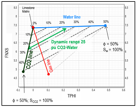
TPHI vs FNXS crossplot for estimating carbon dioxide
saturation Sco2
QUANTITATIVE
METHODS FOR CO2 LOG ANALYSIS
Quantitative analysis of carbon
dioxide saturation (Sco2) is possible using capture cross section
(SIGMA), neutron porosity (TPHI), or fast neutron cross section
(FNXS) using the classic log response equation by substituting CO2
parameters for the hydrocarbon terms. CO2 has zero hydrogen index so
TPHI reads total porosity only if the zone is 100% wet. For a zone
filled with super-critical CO2, TPHI will read near zero porosity.
SIGMA and FNXS also have very different properties for CO2 compared
to those for water, so all three terms can be used as CO2 saturation
indicators. See Table 1.
Here is the log response equation for the SIGMA measurement with
only CO2 and water in the porosity:
1: SIGMA = PHIe * Sw * SIGw (water term)
+ PHIe * (1 - Sw) * SIGco2 (carbon dioxide term)
+ Vsh * SIGsh (shale term)
+ (1 - Vsh - PHIe) * Sum (Vi * SIGi) (matrix
term)
Where:
SIGco2 = log reading in 100% carbon dioxide
SIGi = log reading in 100% of the ith component of matrix rock
SIGMA = log reading
SIGsh = log reading in 100% shale
SIGw = log reading in 100% water
PHIe = effective porosity (fractional)
Sco2 = carbon dioxide saturation in reservoir (fractional)
Sw = water saturation in reservoir (fractional)
Vi = volume of ith component of matrix rock
Vsh = volume of shale (fractional)
WS(ppm) = water salinity NaCl
equivalent (parts per million)
This equation is solved for Sw by assuming all other variables are
known or previously calculated:
2: SIGw = 22.0 + 0.000404 * WS(ppm)
3: SIGm = Sum (Vi * SIGi)
4: PHIe = TPHI from baseline log before CO2 injection, OR from
open hole logs
5: SWtdt = ((SIGMA - SIGm) - PHIe * (SIGco2 – SIGm) - Vsh * (SIGsh
- SIGm))
/ (PHIe * (SIGw - SIGco2))
6: Sco2 = 1 - SWtdt
Similarly for FNXS:
7: FNXSm = Sum (Vi * FNXSi)
/ (PHIe * (FNXSw - FNXSco2))
8: SWfnxs = ((FNXS-FNXSm)-PHIe*(FNXSco2-FNXSm)-Vsh*(FNXSsh-FNXSm))
/ (PHIe * (FNXSw - FNXSco2))
9: Sco2 = 1 - SWfnxs
And for TPHI:
10: TPHIm = Sum (Vi * TPHIi)
11: SWtphi = ((TPHI-TPHIm)-PHIe*(TPHIco2-TPHIm)-Vsh*(TPHIsh-TPHIm))
/ (PHIe * (TPHIw - TPHIco2))
12: Sco2 = 1 – SWtphi
The FNXS model has the best resolution for CO2 monitoring. FNXS
values for helium and nitrogen are reported to be similar to CO2 so
the Pulsar log can be used to evaluate helium wells through casing.
Other uses include monitoring natural gas and hydrogen storage
reservoirs.
CO2 LOG ANALYSIS
EXAMPLE
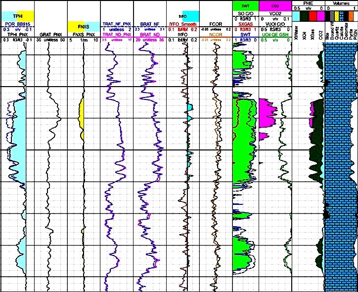
Examples of CO2 detection and quantification at current
reservoir condition. Different gas indicators are presented,
including Sigma, Neutron count rates and porosity, Fast
Neutron Cross Section, and its deviation from Fast Neutron
Cross Section of matrix components in presence of gas.
SIGMA, TPHI, FNXS end points calculated based on gas density
and composition. Lithology and
porosity are measured based on induced gamma ray
spectroscopy combined to TPHI and FNXS, eliminating the need
for open hole logs.
TABLE 1:
NUCLEAR PROPERTIES FOR TDT ad PULSAR LOGS
Material Sigma
(c.u.) TPHI FNXS (1/m)
Quartz 4.55 –0.03 6.84
Calcite 7.08 0.00 7.51
Dolomite 4.70 0.03 8.51
Orthoclase 15.82 –0.05 6.33
Albite 7.65 –0.04 6.69
Anhydrite 12.45 –0.03 7.14
Pyrite 90.53 0.01 6.60
Bituminous Coal 15.79 0.68 7.72
Dry Illite 20.79a 0.22 8.06
Wet Illite 21.00 a 0.34 8.02
Dry Smectite 14.36 a 0.29 8.36
Wet Smectite 19.23 a 0.68 8.60
Kerogen (CH 1.3g/cc) 20.18 0.98 9.07
CH4 (0.05 g/cc) 2.50 –0.05 0.67
CH4 (0.15 g/cc) 7.50 0.21 2.01
CH4 (0.25 g/cc) 12.50 0.47 3.36
Oil (C3H8 0.5g/cc) 18.21 0.78 5.44
Oil (C3H8 0.6g/cc) 21.85 0.97 6.53
Diesel (CH1.8 0.89 g/cc) 23.30 1.08 7.98
CO2 (0.6 g/cc) 0.03 –0.12 2.24
Water 0 ppm 22.2 1.00 7.800
Water 200,000 ppm 97.2 0.90 7.36
ACKNOWLEDGEMENTS
Thanks to Chiara Cavalleri of Schlumberger for contributing content
for this article, including examples and Table 1. Thanks also
to Sandra Bleue for acting as research assistant on the Pulsar log
and the fast neutron cross section (FNXS) measurement.
REFERENCE
Fast Neutron Cross-Section Measurement Physics and Applications
Tong Zhou, David Rose, et al
SPWLA 57th Annual Symposium, 25 – 29 June 2022
|